Heat Pipes: What, How, and Where?
- May 22, 2020
- 11 min read
What are heat pipes, how do they work, and where are they used? Discover all of this and more below!
No matter how much heat pipes continue to develop in the future, one thing is clear. Their rich history, simple mechanics, and varied applications make them a scientific development worth talking about!
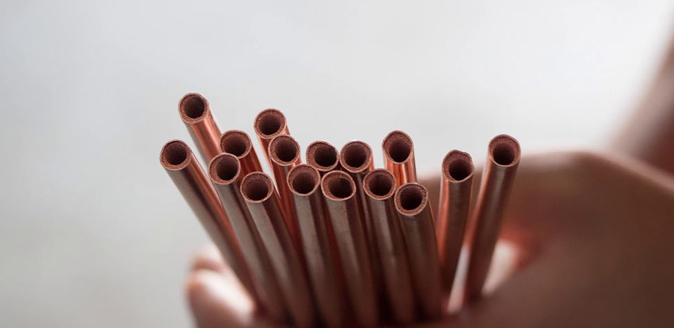
Image taken from https://www.youtube.com/watch?v=p71V6zLybig
What are Heat Pipes?
Heat pipes are small metal rods that have an extremely high thermal conductivity. They are used for heat management in electronics, engines, lighting fixtures, avionics, spacecrafts, and much more. A heat pipe is used to transfer heat in a system from an undesirable location to an acceptable one. Many different materials can make up a heat pipe, but the most common industrial heat pipe has copper as the metal and water as the working fluid. This is due to the material availability, cost, and excellent mechanical properties [2]. The thermal conductivity of a copper-water heat pipe system can range from 10,000-200,000 W/mK [1]. Two metals that are widely regarded as having very high thermal conductivities, aluminum and copper, only have thermal conductivities of 180 W/mK and 390 W/mK respectively [1]. So as you can see, a heat pipe is orders of magnitude better at transferring heat than aluminum and copper on their own. This is due to the unique design of incorporating water as a “working fluid” which will be discussed more in the “How” section. A cool demonstration done by The Action Lab, as seen in Figure 1 below, shows a person holding a heat pipe in his hand and cutting through an ice cube like it is butter [2]. The heat pipe is able to quickly transfer enough heat from his hand to heat up the opposite end of the pipe and melt the ice!
Figure 1. A heat pipe melting through ice due to the heat transfer from someones hand. Taken from 3:10 in https://www.youtube.com/watch?v=OR8u__Hcb3k
Heat pipes were originally patented in 1942 by R.S. Gaugler from the General Motors Corporation in Ohio, USA [3]. The intent was to use them in refrigerators, and the concept is a bit counterintuitive to the description above. While the heat pipe in Figure 1 heats up very quickly, the side of the pipe in the man's hand also cools down very quickly. This is because the pipe is removing and applying heat and at an equal rate. No heat is generated within the system, only transferred through the system, so according to the basic heat balance equation:
[Heat in] - [Heat out] + [Heat generated] = [Accumulation of Heat]
[Heat generated] = [Accumulation of Heat] = 0 in the case of the heat pipe, therefore
[Heat in] = [Heat out]
The heat from the man's hand is transferred to the ice, and the “cold” (scientific term is “coolth”) from the ice is transferred to the man's hand at an equal rate. This concept of drawing heat away was the intent of Gaugler’s original patent. Figure 2 shows his refrigerator concept as proposed in the patent in 1942. The ice in the bottom of the unit would make the pipe in the unit cool, and any heat inside the unit would get transferred down to the ice, drawing heat away from the food and keeping the interior of the refrigerator cold.

Figure 2. The refrigeration unit proposed in Gauglers patent [3].
Unfortunately, other coolant liquids proved better suited for refrigerator applications than Gaugler’s heat pipe, but his concept was suited for applications far beyond refrigerators. These will be discussed in the “Where” section, but for now, let's talk about how the heat pipe is able to transfer heat at such a fast rate.
How Does a Heat Pipe Work?
Figure 3 below comes from Advanced Cooling Technologies, a leading provider of heat pipes located in Lancaster, PA. Reference 1 is the webpage with this image. It gives a good visual to discuss how a heat pipe works.

Figure 3. Dissecting the inside of a heat pipe [1].
Heat pipes can contain a variety of metals and a variety of working fluids. Possible metals include nickel, stainless steel, or molybdenum. Possible working fluids include helium, lithium, or sodium [3]. The type of metal and working fluid used depends on the temperatures the heat pipe will operate at. For example, helium would be used for cryogenic temperatures such as pipes used on spacecraft exteriors, whereas sodium and lithium would be used in high temperature applications exceeding 1000°C such as pipes used in engines [4]. For simplicity's sake, let's consider the most common purpose copper-water heat pipe, which operates from about -20 to 200°C [4].
The way a heat pipe transfers heat can be summarized as follows, with a more in depth explanation following:
Heat enters the pipe in the evaporator section
Heat causes water → steam phase change to occur. The water is contained in the wick, and the steam enters the center of the pipe.
Due to the pressure gradient formed from the temperature difference, the steam travels to the condenser section
Steam → water phase change occurs in condenser section, releasing heat (usually into a heat sink such as aluminum)
Through capillary action, the water returns through the wick back into the evaporator section, where step 1 repeats itself.
The envelope (see Figure 3) is the outer portion of the heat pipe, and it is made of copper. This simply acts to hold everything in place. It is vacuum sealed, and can be round or flat depending on the application.
Next is the working fluid. This is the water, but more specifically steam. The water will be contained in the wick (the wick will be described in more detail later). Once the water is heated, the steam enters the middle section of the heat pipe. Water needs about 2257 kJ/kg of energy to turn to steam, so a lot of heat can be absorbed in this process [5]. Since the evaporator section of the pipe is hot, and the condenser section is cold, the temperature difference will create a pressure with enough force to push the steam towards the condenser section. A slightly imperfect but useful analogy to understand how a temperature gradient creates a pressure is to think about wind. Wind is formed by pressure gradients in our atmosphere due to differing temperatures of gas molecules in the air. When the temperature gradient is larger, the pressure is larger, and the wind blows faster. Similarly, when the evaporator and condenser sections of the heat pipe have a greater temperature gradient, the steam will travel faster, meaning the heat pipe will work even better. Also, if the steam is treated as an ideal gas, then PV=nRT holds true, which shows that an increase in temperature will equal an increase in pressure, explaining the above with a more scientific approach.
Once the steam reaches the condenser section, it will cool and transform back into water, releasing heat. There is typically a heat sink (commonly made out of aluminum fins) around the condenser section of the pipe to draw heat away from the device. Next, the water enters the wick and is pushed back to the evaporator section through capillary action. This process continues to repeat itself to carry heat from the evaporator section to the condenser section very effectively - leading to the heat pipe’s high thermal conductivity.
The most important function of the copper metal is the wick section. The wick section is responsible for holding the water and transporting it from the condenser to the evaporator section of the pipe through capillary action. There are three common geometries for the wick: sintered, mesh, and grooved. They are shown in Figure 4 below.
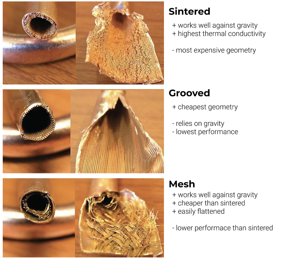
Figure 4. Sintered, grooved, and mesh heat pipes pros and cons. Photos taken from [6].
The most common geometry is usually sintered, although this may vary depending on the source. This is because it works well against gravity and has the highest thermal conductivity, although it is also the most expensive one [7]. A sintered wick is created by applying a copper metal powder inside the tube and heating it to bake it onto the walls [6].
The grooved heat pipe is the cheapest and the lowest performance because it relies on gravity [6]. The evaporator must be below the condenser for a grooved wick to transfer water back to the evaporator, which is not always a possible system setup. However, when this design is possible, this is a cheap alternative to the mesh geometry.
Lastly, a mesh wick is also arguably the most popular geometry. This is because it can work well against gravity and is cheaper than the sintered one. The mesh wick almost looks like a screen door, and different meshes can achieve different properties (and different prices too). If the heat pipe needs to be as thin as possible to be used in a given system, the mesh wick is best suited [7].
Now that we understand the basic theory of how a heat pipe works, let's discuss a few limitations to the thermal conductivity. It is first important to note that the thermal conductivity of a heat pipe varies greatly, unlike the thermal conductivity of a solid piece of copper. Thus, no one specific value can be given for a heat pipe's thermal conductivity, and in industry they are generally reported as ranges or on an individual basis [7].
A general equation for thermal conductivity is:
K= (QL)/(AΔT)
In this equation, K is thermal conductivity, Q is power transported, L is length, A is cross sectional area, and ΔT is the temperature difference, in Kelvin, across the entire length of the heat pipe.
So, length and cross sectional area are important design parameters to consider to obtain the highest thermal conductivity. An increase in the length of the heat pipe will result in an increase in thermal conductivity. Celsia, a heat pipe manufacturer based in Santa Clara, CA, reports values for thermal conductivity of heat pipes heated with a 75 watt power source [7]. A 75mm long heat pipe has a thermal conductivity of 10,000 W/mK whereas a 200mm long heat pipe has a thermal conductivity of 44,000 W/mK [7]. So, ~doubling the length of the heat pipe results in ~quadrupling the thermal conductivity. So, when designing heat pipes, design them to be as long as possible to get the highest thermal conductivity possible.
Cross sectional area is another factor affecting thermal conductivity. It is common to bend a pipe to fit the specific needs of the system it is cooling. Bending a pipe at a 90 degree angle will reduce the cross sectional area by ~3-5x [8]. This decrease in cross sectional area will decrease the thermal conductivity, contrary to the equation seen above. This is because reducing the cross sectional area will also reduce Q, which will have a greater effect on thermal conductivity than area. A 90 degree bend in a pipe will reduce the maximum power transported (Qmax) by about 5%. Data reported by Celsia says a 2.5mm pipe has a Qmax of about 52W, but bending it 90 degrees results in a Qmax of 49.45W, which will in turn decrease thermal conductivity [9].
Further research to improve the thermal conductivity of heat pipes is being done on nanoparticles in the working fluid. The nanoparticles are typically metallic and good thermal conductors such as silver, iron oxide, and titanium. Evidence has been documented that using nanoparticles in the working fluid can improve the thermal conductivity by up to 60%!4
Now that we know what a heat pipe is and how it works, let's now move on to where they are used.
Where are Heat Pipes Used?
I first want to note that this section is wholly incomplete. The applications for heat pipes continues to expand as more research is conducted. However, this section gives a good overview of the many diverse applications for the heat pipe. I tried to include in depth explanations of applications I thought were most interesting and significant - but I probably missed many simply because there are so many.
In general, heat pipes can be used to separate a heat source and sink, control temperature, to act as a thermal diode and switch, to control heat flux transformation, and the flatten temperature [3]. The working fluid can change depending on what temperature range the heat pipe can function in, so there is a wide range of applications. The lower temperature range heat pipes, typically containing liquid helium, are used in particle accelerators, nuclear reactors, and on spacecrafts [3]. Magnesium is a common material for a heat pipe used on a spacecraft because of its low weight with good thermal conductivity. A heat pipe’s weight is the number one property keeping it from being used more on spacecrafts. Lighter fluid pumping and thermal storage technologies are the main competitors. However, loop heat pipes (LHP’s) are gaining traction as a solution to cool spacecrafts [3]. Research on variable conductance heat pipes (VCHP’s) was expanded after an experiment named CAPL-3 was carried out on the STS-108 satellite [3]. A heat pipe radiator used on the International Space Station is shown in Figure 5 below. It should be noted that LHP’s and VCHP’s are much more expensive than the bare bones heat pipe described earlier.
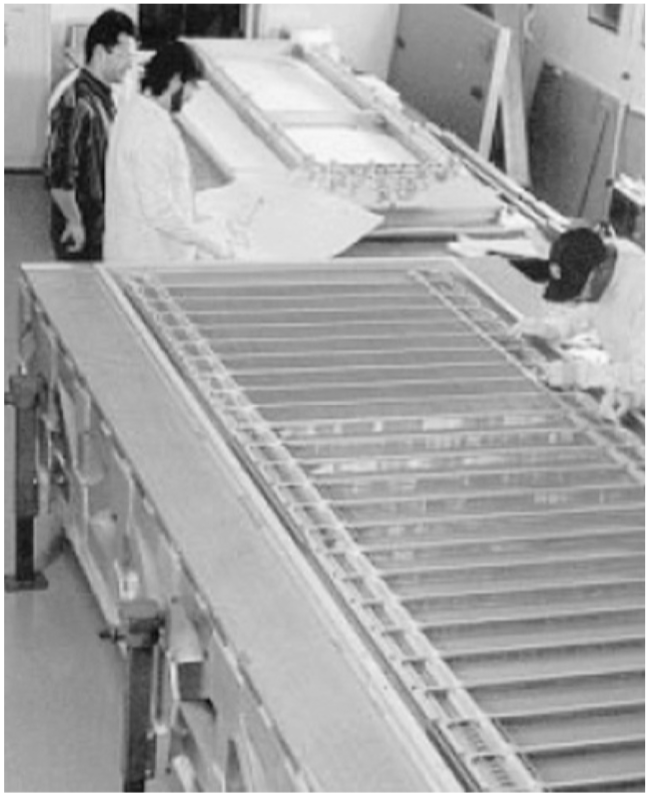
Figure 5. A heat pipe radiator that will be used on ISS. Image taken from [3].
More mid-temperature range heat pipes are used for cooling electronics, and more practical industrial applications. Heat pipes were used in the 1970’s on the trans-Alaska oil pipeline to prevent permafrost from melting. The permafrost supported the pipeline, and the structural integrity of the pipeline would be compromised if the permafrost it sat on melted. Heat pipes were able to solve this issue, keeping the permafrost frozen. The heat pipes used on the pipeline were only about 9-23mm in size, and McDonnell Douglas Corporation produced about 100,000 heat pipes total for this project, costing about $13,000,000 in total [3]. Preserving permafrost is a large application of heat pipes, and often uses ammonia as the working fluid. Figure 6 below shows a schematic of how heat pipes are used to keep permafrost frozen.
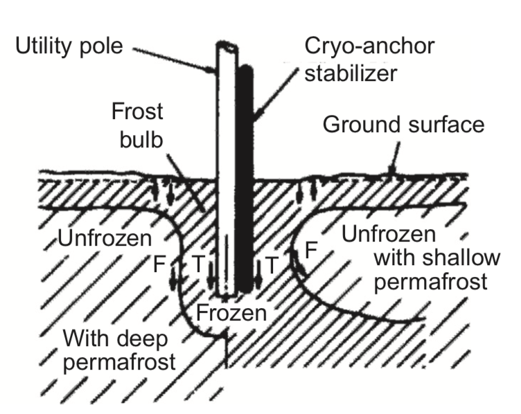
Figure 6. How a heat pipe is used to keep permafrost frozen. Image taken from [3].
Another mid temperature application is in energy storage systems. In general, an energy storage system functions best when kept cool. Thus, heat pipes are used in hot water tanks, air conditioner systems, and refrigerators [3]. Many large refrigeration units in restaurants and grocery stores will utilize heat pipes as an additional cooling technology in addition to the conventional cooling technologies. Figure 7 below shows how the heat pipes aid in keeping the refrigerator cool.

Figure 7. How a heat pipe helps keep a refrigerator cool. Image taken from [3].
Also, heated floors and driveways commonly use heat pipes [3]. Sometimes, heat pipes are used on railroads where a lot of heat is generated by the massive amounts of friction generated between the wheels and the track. In these applications, the Earth is used as a heat sink [3]. Heat pipes are also widely used in all types of electronic systems, from computers to tablets to large industrial factory setups. Lastly, a very common application of heat pipes is to cool in flight entertainment systems aboard aircrafts. With things like lights, wifi, chargers, and televisions provided to passengers aboard an aircraft, not everything can use the aircraft’s cooling systems. So, heat pipes are often added under passengers seats to help cool the electrical systems on board, as seen in Figure 8 below.

Figure 8. How heat pipes are used to cool passenger seats aboard aircrafts. Image taken from [3].
Some higher temperature range applications involve solar energy. Heat pipes are used to absorb solar energy (heat) and transfer this heat to water. There are historical accounts of heat pipes being used to absorb solar energy to heat a home [10]. Another high temperature application is chemical reactors. If the reactor can stay uniform in temperature, achievable using heat pipes, it will produce a higher quality product. Thus, heat pipes will often be used to increase the profit and value of chemical reactor companies.
The applications of heat pipes can continue for many pages, but these are some of the big hitters. There is also research being done currently, a large push being incorporating nanoparticles into the working fluid for improved thermal conductivity as discussed earlier.
No matter how much heat pipes continue to develop in the future, one thing is clear. Their rich history, simple mechanics, and varied applications make them a scientific development worth talking about!
References
https://www.1-act.com/wp-content/uploads/2017/07/Copper-Water-Heat-Pipes-WEB.pdf
D. Reay, R. McGlen, and P. Kew. "Heat Pipes: Theory, Design, and Applications." (2014).
https://www.intechopen.com/books/electronics-cooling/heat-pipe-and-phase-change-heat-transfer-technologies-for-electronics-cooling
https://www.ck12.org/c/physics/heat-temperature-and-thermal-energy-transfer/rwa/Boiling-Water/
https://www.radianheatsinks.com/heatpipe/
https://www.richardsonrfpd.com/docs/rfpd/Wakefield_Heat_Pipe_Selection_Guide.pdf
https://celsiainc.com/heat-sink-blog/heat-pipe-design-guide/
L. Vasilliev. "Heat Pipe Research and Development in the USSR." (1989).


Comments